Reimagining the Veterans Memorial Tunnels
January 13th, 2015 | Published in Google SketchUp
 |
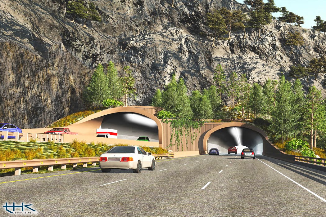
| One of the final renderings of the proposed tunnel design – SketchUp model rendered with Vue. |
Tell us a little more about this project.
These tunnels (formally known as the Twin Tunnels) were originally built in 1961. This project focused on improving mobility within the I-70 corridor by widening both tunnels to three lanes with wider shoulders. The project also focused on addressing safety and creating unique features to serve as gateways for the area.
The previous design of the tunnel portals created a feeling of driving into a headwall, which caused motorists to brake and slow down when approaching the tunnels. The new design resolves this problem by integrating a spiraling tunnel portal that welcomes motorists into the tunnel gradually. These spiraling tunnel portals are the result of evaluating multiple design options on a variety of criteria.
Did you work with any data that was imported into SketchUp?
Yes, most of this 3D model was based on imported data. The existing terrain information was collected in the field with LiDAR, and the LiDAR data was converted into a TIN (Triangulated Irregular Network) mesh in Microstation. Microstation was used because that’s the main software the transportation engineers use. The Microstation mesh was then exported to AutoCAD .dwg files as both a mesh and as contour lines. We were able to import the mesh file directly into SketchUp, and the contour file was used to create proposed grading files in AutoCAD. The proposed grading files, as well as the plan view geometry (road layout, tunnel layout, retaining walls, etc.) were all created in AutoCAD and the .dwg files were imported into SketchUp. Once in SketchUp, the proposed contours became meshes via the From Contours Sandbox tool, and they were then combined with the existing grade meshes.
How did SketchUp help in the decision-making process?
This project used a Context Sensitive Solutions (CSS) approach, which involves creating and evaluating a number of options based on a variety of criteria. SketchUp was used to arrive at the final options that were evaluated in the CSS process, and for evaluation during the actual CSS process. Leading up to CSS, over a dozen different design options were created and explored in meetings. For these meetings, SketchUp was more useful than final renderings because we were able to look at any view in real time, as well as make design changes to explore additional options. During the CSS evaluation, SketchUp was used to compare four options side-by-side.
 |
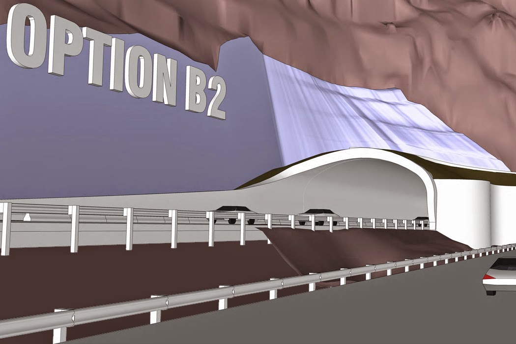
| One of the west portal options in SketchUp. The pinkish area is existing terrain, and the purplish area is proposed (the big wall of purple is a large cut where rock was blasted away to create enough space for the wider tunnels). |
How did you communicate or collaborate with other colleagues and consultants?
We used one main SketchUp model with multiple groups and layers. I’m a bit of a grouping (and components) fanatic; it keeps models organized and the file size down. I mainly use layers for separating visual options, which was perfect for this project. One little trick was to place 3D text with the name of the design option in a visible place in the model (as seen in the image above) and put it on the same layer as the geometry for that layer. Whenever Option B was being shown, “Option B” text was visible; this helped reduce confusion.
I think the SketchUp images do a pretty good job of showing how we used SketchUp as a design tool, but what isn’t shown is how interactive it was for meetings. Being able to analyze and compare over a dozen options from any view, modify those options on the fly, and create new options while in meetings was invaluable. To work efficiently on the fly, the model needs to be created with that objective in mind. For example, having the different options on appropriately named layers allows you to quickly compare the options at the request of meeting attendees. Having the model neatly grouped allows you to easily modify pieces without affecting the whole model (be sure to know which pieces are groups and which are components). These in-meeting modifications to the model often are not as clean as the overall model and may require some clean up back at the office. Typically, I will save the ‘meeting’ version of the model, but only use it as a reference to make the refined edits to the final model.
Were there any SketchUp extensions that helped with this project?
I use extensions every time I open SketchUp. Some that I use on almost every project – including this one – are Weld, Tools On Surface, Joint Push/Pull Interactive, Selection Toys, Bezier Spline, and PathCopy.
The most challenging piece of the model to create was the spiraling tunnel extensions. I went through a number of trials to get the geometry correct; some of these trials used extensions such as Extrude Tools, Artisan, Curviloft, and Follow Me & Rotate. ThomThom recently released an extension called Bezier Surface that would have been really helpful had it been available when I was working on this model!
Also, the ivy that is seen in the final Vue renderings was created in SketchUp using the SketchUp Ivy extension – this wasn’t added to the design until I was already working in Vue; that’s why the ivy doesn’t show up in the SketchUp images.
 |
|
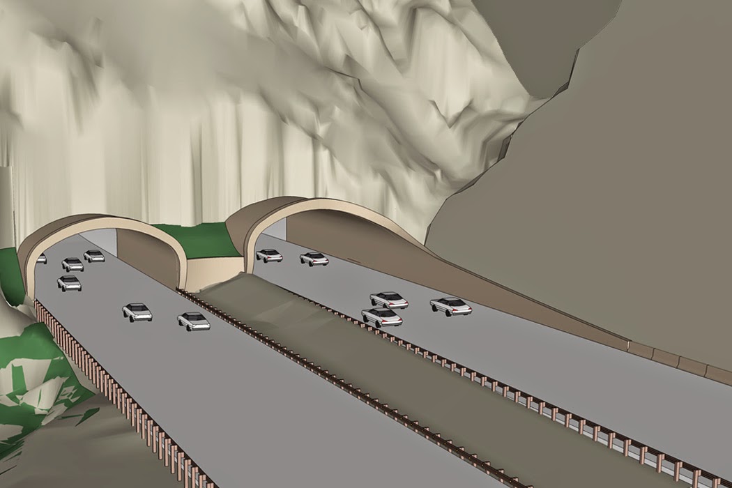
SketchUp view of the east portal exploring the spiraling hood extension at the tunnel entrance. |
Tell us about the transition from SketchUp model to the final Vue renderings.
The transition from SketchUp to Vue is fairly simple. I typically change the SketchUp materials to bright solid colors so that I can easily differentiate them in Vue (unless there’s a SketchUp image texture I want to use in Vue). After cleaning up any unnecessary pieces of the model (such as unused options), I export the model to an .obj file and import that into Vue. All of the vegetation (except the ivy) is added in Vue. The boulders and talus slopes were also created in Vue. Vue recognizes objects based on material, so it is fairly easy to create and assign materials one-by-one for the model. The process typically involves a lot of quick, low quality test renders to fine tune the materials, lighting, camera, and atmospheric settings. Once these are all finalized, the high quality final renderings can be created – which can take a while. Some of the renderings for this project took 16+ hours to render! All that remains after that is post-processing work in Photoshop.
 |
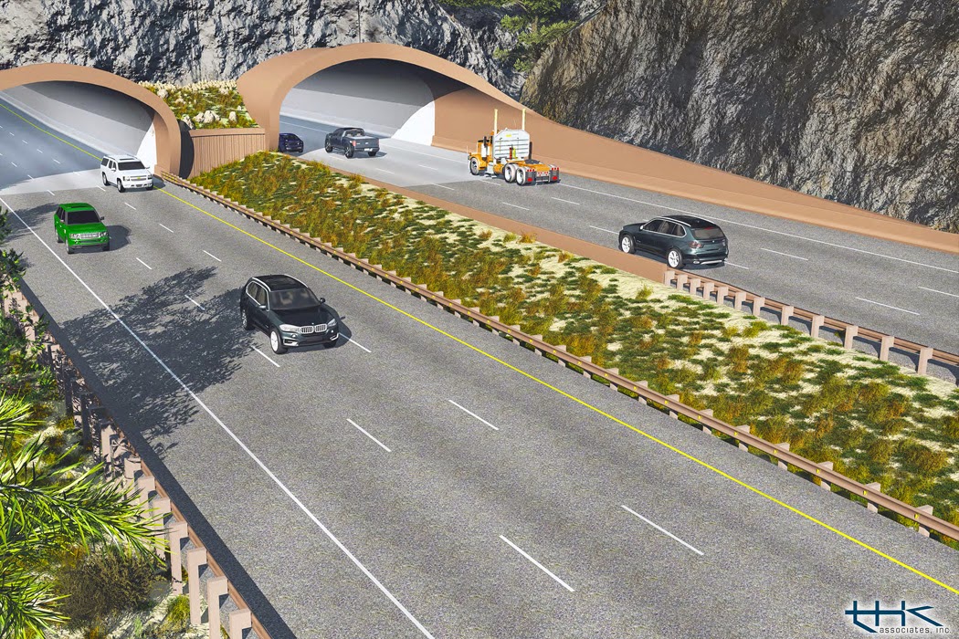
| Final rendering of the east portal. |
How do you go from SketchUp model to tunnel construction?
For this project, much of the “base pieces” were already engineered and into construction documents when the SketchUp modeling began. For example, the core tunnel structure/bore, the roadway alignment, and the utilities were all pretty much set. The configuration of the tunnel extension walls, retaining walls, and proposed grading were all items that became defined by decisions from the SketchUp model. For these items, the beginnings of the construction documents were already in place from creating the linework in AutoCAD. From there, we simply had to bring these drawings to 100% construction documents and the General Contractor installed them. The General Contractor was involved in many meetings leading up to construction where we used the SketchUp model to better explain details of the design.
Posted by Josh Reilly, SketchUp Team